Transfer of the immediate discharge of the electrical energy directly to the earth by means of the low resistance path is known as the earthing.
Instrumentation Earthing
Main objective of the earthing system in plant is described as below:
- It provides low impedance path to ensure the proper function of system under fault condition
- It ensures that personnel are not exposed to unsafe potential due to uncleared fault
- It ensures compliance to EMC requirements
- IS earth avoids ignition sources in Hazardous Area.
Items or equipment which require earthing, are but not limited to below,
- field instruments,
- control system cabinets,
- analyzer shelters,
- junction boxes,
- enclosures,
- ducts,
- cable trays,
- stanchions,
- field local panels,
- Consoles,
- Motors,
- Tanks,
- vessels,
- pipes,
- steel structure, etc.
This article mainly focuses on earthing requirements for instrumentation items of any industrial plant.
Types
There are mainly 3 types of earthing systems provided for instrumentation.
- Safety Earth (SE) / Dirty Earth / Protective Earth / Electrical Earth / Power Earth
- Instrument Earth (IE) / Electronic Earth / Reference Earth / Clean Earth / Signal Earth
- Intrinsic Safety (IS) Earth for IS circuit. This is only required when you have IS instruments.
Instrument Earth
The primary aim of the instrument earth/signal earth is to provide a low impedance path to the noise currents induced by RFI/EMI, which may result in the induction of faulty unwanted noise signals into the analog signals.
Shields of Single pair /Multi pair analog instrument signal cables are connected to this earth (IE).
Safety Earth
Undetected earth faults pose safety risks to personnel also may lead to safety hazards such as equipment malfunctions, fire, and electric shock. That is why we need electrical earth / Safety earth.
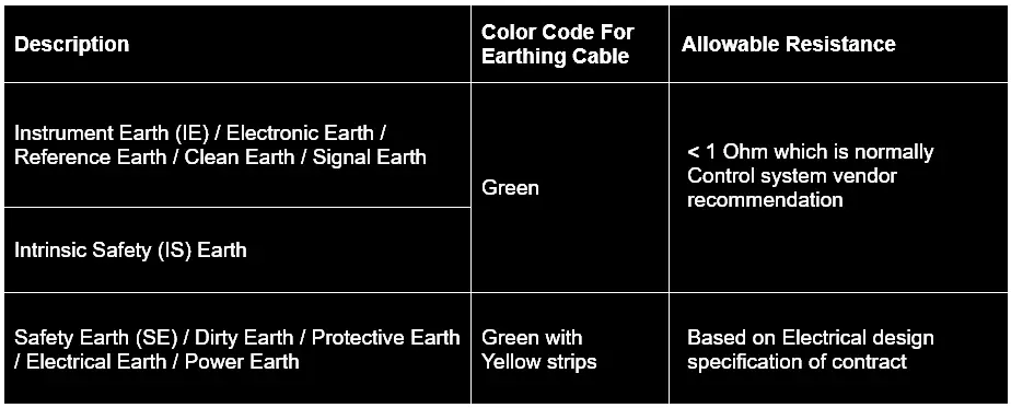
Earth Resistance
Allowable earth resistance as per codes or control system vendor recommendation should be considered for Instrument Earthing system design.
Below is a reference table that can be updated based on the project-specific requirement.
There should be isolation between each type of earthing mentioned above. If there is no isolation which means that the purpose of the above earthing requirement will not be fulfilled.
There are mainly two areas in which earthing system is envisaged.
- Indoor (Building like control room, Switch-gear rooms etc where cabinets/panels/consoles etc are installed)
- Outdoor (Process area where instruments and related installation items are installed)
control panels inside the control room fall under the Indoor type. Depending upon the cabinet’s functions each type of earthing bars are provided.
Control room equipment including system cabinet & marshaling cabinets, power distribution panels, Packaged control system cabinets, Workstations, Auxiliary consoles, printers, etc. should be considered for earthing requirement.
e.g. System and marshaling cabinets should have – SE, IE and IS Earth bars.
Network cabinets / server cabinets / Power distribution panel should have – SE only.
Within the Cabinet, the Instrument Earth bar shall be isolated from the Safety Earth bar by mounting the Instrument Earth bar on insulating buses.
All the instrument earth bars in the cabinets should be connected to a common instrument earth bar provided in the false floor / Cable cellar using an insulated redundant copper conductor cables.
This common Instrument Earth bar shall be further connected to the nearest Instrument earth grid using copper cables.
It should be agreed with the Control system supplier for earthing philosophy of Cabinet’s earth bar connection with the building earth bar network. E.g. Star connection or series connection.
Earthing philosophy should cover Scope of supply, grounding wire/strip sizes, earth stud size, wire color as a minimum.
Series Earth Connectivity
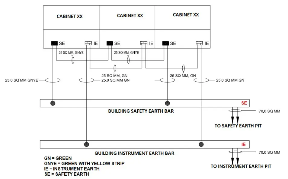
All the safety earth bars in the cabinets should be connected to a common safety earth bar provided in the false floor / Cable cellar using insulated redundant copper conductor cables.
This common Safety Earth bar shall be further connected to the nearest safety earth grid using copper cables. The Main Earth grid conductor size can be calculated based on the desired fault current within the required time to be earthed.
Ultimately, this network/grid is connected to earth pits. The surrounding soil of the earth pit must be kept moist. The effect of the soil temperature on soil resistivity is more influencing near and below the freezing point, which will result in the installation of the earth electrode at the depth to which frost will not penetrate.
Good Practices
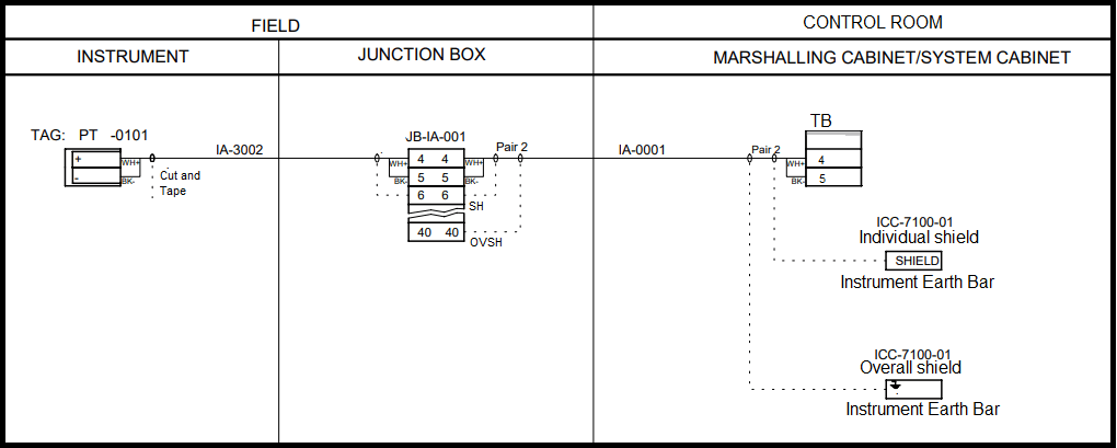
Similarly, for IS cable, individual and overall shield shall be connected to the IS earth bar inside the cabinet.
Ensure continuity of all earth cables up to earth bar & up to earth pits.
- Cable armours shall be earthed at both ends for lightning protection i.e. at the junction box and at the control system end. Since the Junction box body and Control system cabinet body is connected to the Safety earth bar, cable armors are ultimately connected to the safety earth.
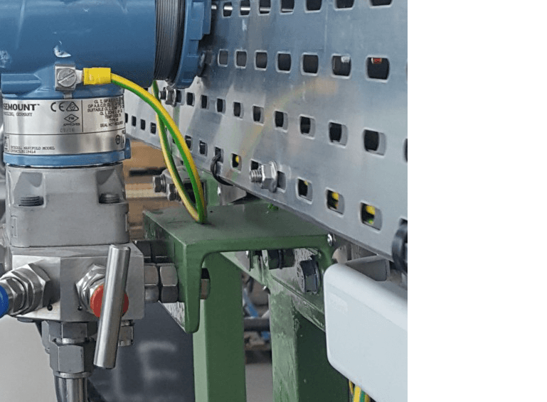
- All instruments (24V DC or 110 V /220V AC operated) body should be earthed to the nearest field safety earth bar located on the Steel structure.
- Earth continuity should be ensured between tray, tray fittings, and tray sections. This will be ensured by Earth cable/strips at every 25 meters of tray length.
- Earth bar connection should be such that painting should not act as bad contact between earth bar and Structure. continuity shall be ensured.
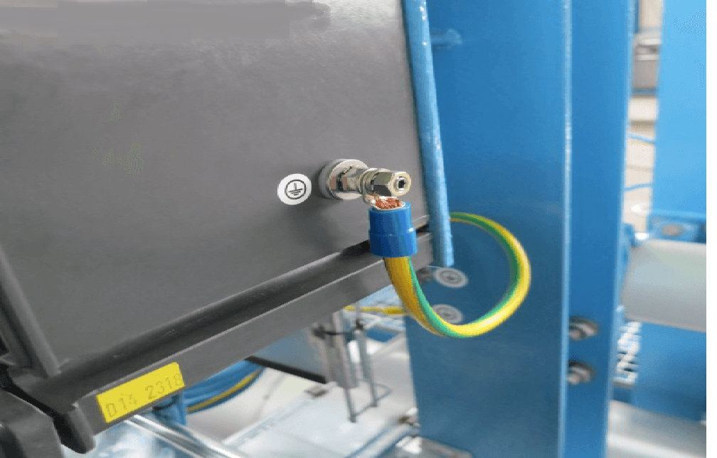
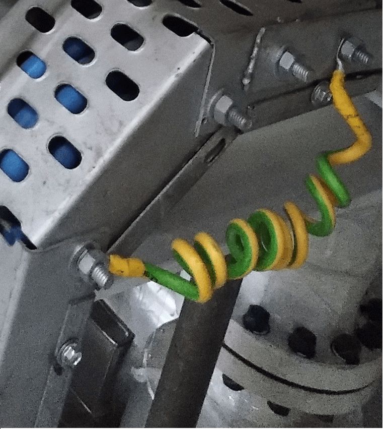
Junction Box Earthing (Safety Earth)
Transmitter Earthing (Safety Earth)
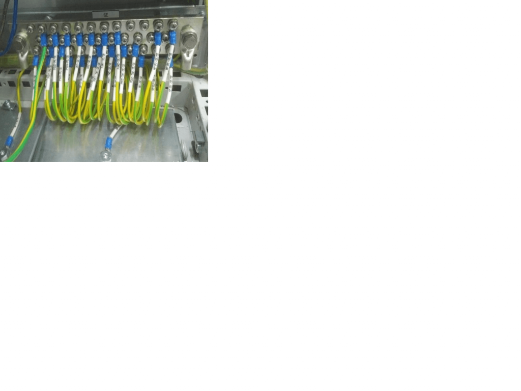
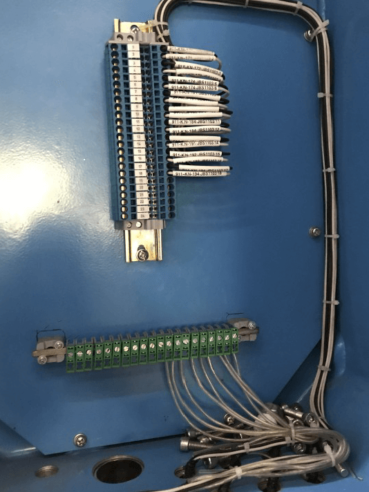
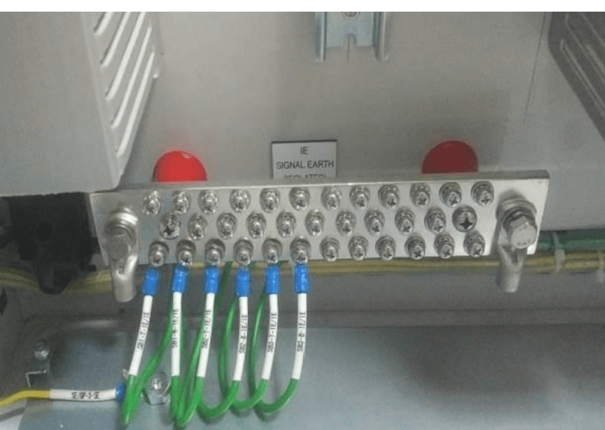
Junction Box shield Termination on Isolated Instrument Earth terminals
Instrument Cable Tray Earthing (Safety Earth)
Instrument Earth inside the Control System cabinet (Isolated from Safety Earth)
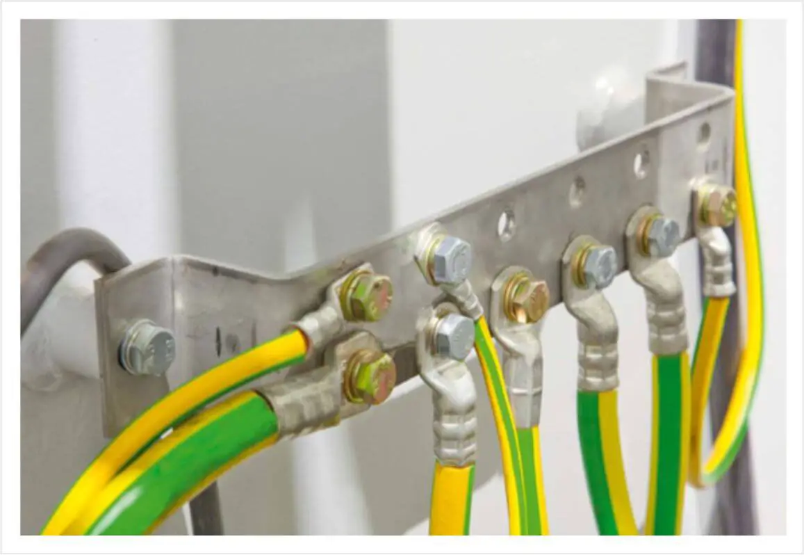
Safety Earth inside the Control system cabinet (Non Isolated)