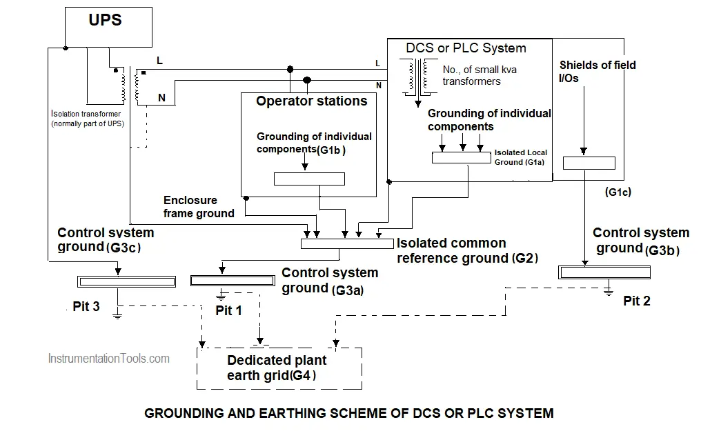
First, let us understand the difference between grounding and earthing.
Whenever the DCS or PLC systems are grounded, they still not connected to the earth. The system has a ground bus bar inside located at an appropriate place to which all internal grounding connection is returned. Once the final ground bus bar is connected to an actual-earth pit or earth grid that the system finally earthed.
Improper earthing or grounding of Distributed Control System (DCS) or Programmable Logic Controller (PLC) may result in either mal-operation of the control system or a controller or failure of electronic cards or sometimes even embedded software gets erased.
In the case of DCS or PLC each cubicle is having a ground bus bar to which the controller chassis, shields can be connected. These bus bars are then returned to a final ground bus bar from where the connection is then taken to earth pit or earth grid.
The earth pit must have a small earth resistance ( much less than 1 ohm). usually, the earth resistance can be measured by a three probe method.
Grounding or Earthing Scheme

Types
There are four layers required for the correct and effective grounding and earthing
- Isolated local Ground (G1)
- Isolated Common Ground Reference (G2)
- Control System Ground (G3)
- Dedicated plant earth Grid (G4)
Isolated local Ground (G1)
Isolated local Ground (G1) is where power supplies, internal power component enclosures, etc., are grounded on a bus bar. This refers typically to one control system.
Isolated Common Ground Reference (G2)
Isolated local Ground (G1) connection from each of the control systems, there within the realm is terminated along with the frame or cabinet or overall enclosures are individually terminated for grounding to create an Isolated Common Ground Reference(G2).
It should be noted that the enclosure earthing minimized the results of Electromagnetic interference.
Control System Ground (G3)
It is where the incoming power supply isolation transformer secondary is grounded along with ground connection obtained from Isolation common ground reference(G2). This control system ground is considered as the final earth pit for that location. It can be terminated on the dedicated plant earth Grid (G4).
The control system ground (G3) or the final earth pit connected to the local control systems should be separate earth pit. Which then can be connected to a dedicated plant earth system. This control system G3 should not be shared with other plant systems.
Dedicated Plant Earth Ground (G4)
The Dedicated plant earth ground (G4) may or may not exist. If exists it is supposed to have the lowest impedance. It consists of many earth pits in a grid fashion.
The cable used for grounding should be in green with yellow marks.
The ground bus bars to be used should be copper bus bars with approximately 10 mm as the thickness and 50 mm in width.
Reference: David Brown, David Harrold, and Roger Hope,” Control Engineering: Control system power and grounding better practice,”
Interest to add any further points? Share with us through below comments section.
Author: R.Jagan
