
Few factors are to be considered or taken care of while wiring a field instrument to control panel.
- Noise Susceptibility Limit
- Grounding of the signal cable
- Type of cable
- Cable Terminations
Based on noise susceptibility limits (NSL) according to IEEE 815 standard, various field instrument signals are classified as below.
Level 1: High to medium susceptibility
Level 2: Low susceptibility
Level 3: Power AC and DC buses
Level 1
High noise susceptibility level to the medium level: Analog signals of less than 50 V and discrete instrument signals of less than 30 V.
Examples of these signals are:
- Foundation Fieldbus
- 4-20 mA and 4-20 mA with HART
- RTD
- Thermocouple
- Millivolt/pulse
- Discrete input and output signals. Example: pressure switches, valve position’s limit switches, indicating lights, relays, solenoid coils.
- All wiring connected to components related to sensitive analog hardware like strain gauges.
Level 2:
Low susceptibility: Switching signals of greater than 30 V. Analog signals greater than 50 V, and 120-240 AC feeders rated less than 20A.
Examples:
- Discrete input and Discrete output DC signals like pressure switches, valve position’s limit switches, indicating lights, relays, solenoid coils.
- Discrete input and Discrete output AC signals including pressure switches, valve position’s limit switches, indicating lamps/lights, relays, solenoids coils.
- 20-240 AC feeders of less than 20 amps
Level 3:
Power AC and DC buses: 0-1000 V with currents of 20-800 amps.
Signal segregation In instrumentation cabling, it is a very useful practice to segregate various signals from one another.
For the finest optimum segregation, each kind of signal (within each noise susceptibility level NSL) shall transmit on exclusively dedicated cables and rout to dedicated junction boxes.
For example, all 4-20 mA signals shall rout on separate cables from all other signals under Noise Susceptibility Limit -1. The same applies to all other signal types. From the junction boxes to the control room, the cables for every Noise Susceptibility (NSL) level can share the identical cable tray or trench.
The separation distance between NSL-1 and NSL-2 and strong electromagnetic interference such as motors, generators, transformers above 100 KVA shall be at least two meters.
The separation distance between NSL-1 and NSL-2 and power cables rated above NSL-3 should be at least 1 to 1.5 meters.
Besides, all emergency shutdown (ESD) signals should have their Own cables, junction boxes, and also marshaling cabinets. They also have to be segregated based on the signal type as discussed cases above.
It is common to use twisted pair wire when wiring process instrumentation. when two wires are twisted together, many of the electromagnetic interferences are canceled out, so twisted pair wiring is more proof against electrical noise than untwisted wiring.
To add another level of protection from the electromagnetic noise is a ground shield is added over the twisted pair cable.
Field interface multi-core cables connected to junction boxes in the field, transmitting conventional 4-20 mA signals from all sorts of field transmitters, individually, are going to be connected to marshaling racks.
From the marshaling cabinet racks, the signals are going to be connected to the I/O cards of the DCS and ESD system cabinets through pre-fab cables.
Also Read: Working of 4-20mA Transmitter
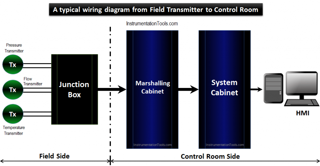
Wiring Diagram of Field Instruments in Control Room
In the following figure below there are various types of field instruments connected to the control room via a field junction box.
A close picture of the connection from a starting point to the destination is shown in it.
Instrument signals can be carried by wiring with a conductor size of at least 18 AWG is recommended. Selecting conductors of 18awg or larger increases the reliability and makes connections easier.
Insulation should be high-quality thermoplastic rated for the voltage to be used ( max 30 V). The standard colors for two-conductor instrumentation cables ar red (+ve) and black (-Ve). Other colors are also available.
The cable jacket should be rated for the proposed use and instrument cable is available for all of the common general uses (e.g. conduit, tray, outdoors, direct burial, etc.).
Also, be sure the jacket is unaffected by any chemicals or oils that it may encounter. If the cable is to be run in conduit, make sure the jacket is of the smooth one. The soft, rubbery jackets make pulling difficult and might result in cable damage.